When And Why To Use Coding Notation
A special coding notation for WeldFEM has been implemented, which in some situations needs to be considered. Those kind of situations will be covered in this chapter.
In general there are 3 cases in which the coding notation must be followed: Thicken PLATE-elements, Modelling Profiles, Specify Joint Type
In some situations, for example at screw connections where washers are in use, it is necessary to unite the thickness of two or more parts into one property, so that the washers stiffness is taken into account. In this case WeldFEM would detect a butt joint, since there are two different properties in use. An example is depicted below.
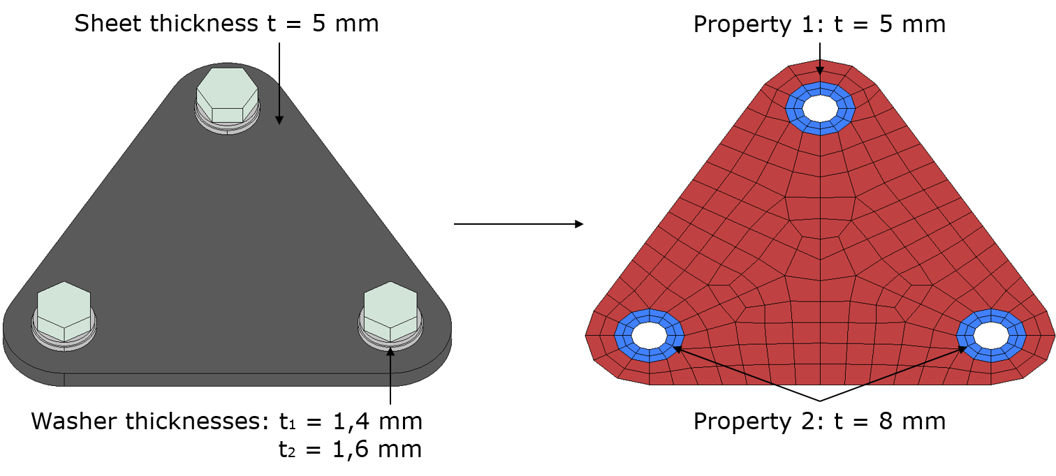
To prevent WeldFEM from detecting a butt joint at the junction of both properties a coding notation is needed. The coding notation only applies to the title of the property itself. It is advisable to rename the properties title which includes the thicknesses of the washers.
The coding notation is as follows: $_*TITLE OF PROPERTY*
Example: $_PL_8 - Sheet + Washers
Implementing this coding notation will make that WeldFEM ignores this property during weld detection. Hence caution is needed, since implementing the coding notation for properties may cause WeldFEM to ignore real welds.
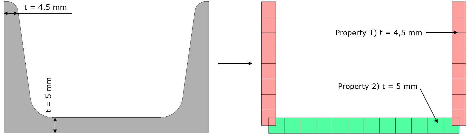
When reducing a profile to a midsurface-based FE-mesh, element joints within the profile may include an angle of rectangular shape or close to 90° and parts of the profile may need different properties for flanges and webs of different thicknesses as shown in the example below. Both mesh features - rectangular angle and change of property - will be detected as possible weld locations by WeldFEM. As profiles are in general manufactured by a rolling or extrusion process, no weld is to be assessed here.
Therefore, a specified coding notation has been implemented in WeldFEM in order to avoid these unwanted "welds" within profiles. The coding notation applies to the titles of the properties and can be used for all kind of profiles.
The profile coding notation consists of three parts:
"@P" signals a profile related property for WeldFEM
"*STRING*" identifies a specific profile
"_" ends the profile designation
So, a property title for a profile is to be established as: @P*STRING*_"TITLE OF PROPERTY"
Note: Avoid using underline in the user defined string, since that is the separation symbol for the coding notation.
Example: title of property #1 @P1_PL_4,5 - U-Profile
title of property #2 @P1_PL_5 - U-Profile
are different properties for different thicknesses, but belong to the same profile "1".
The coding notation allows to associate one user defined string for each individual profile used in the structure to assess. When using the coding notation properly, WeldFEM does not detect welds within the same profile, yet joints between different profiles or between profiles and other parts will be detected. An example of said scenario is depicted below, where profiles are welded together at their junction.
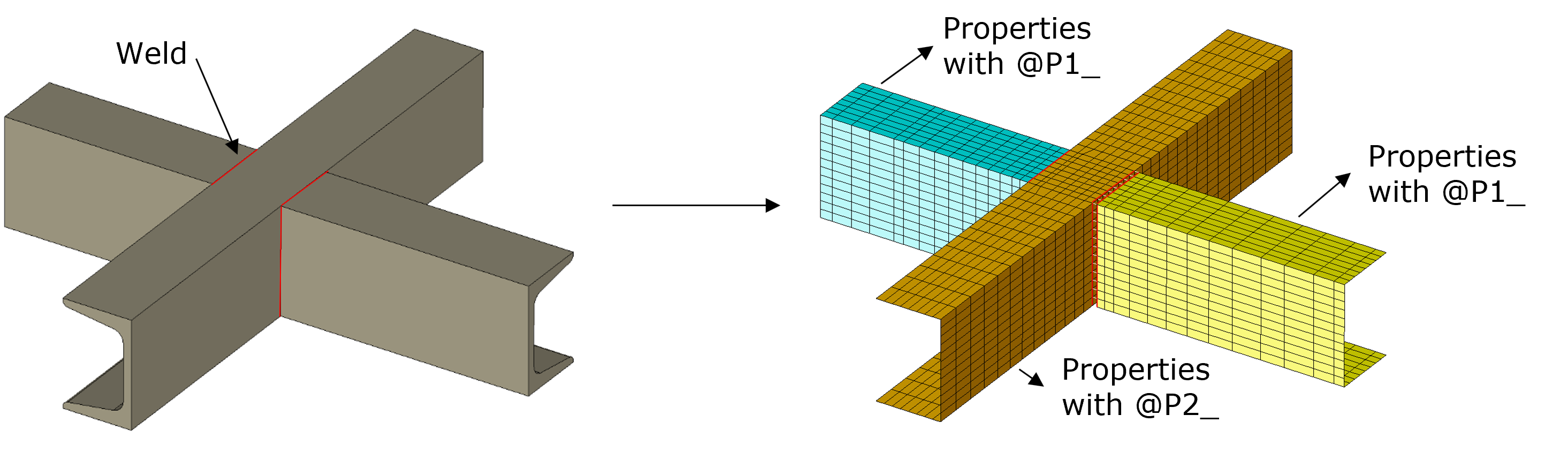
In the example above a welded crossing out of 3 parts of similar U-profiles with 4,5 mm flanges and 5 mm web is shown. Modelling the U-profiles with their correct thickness will require two different PLATE-properties. Naming the profiles in the manner explained above will ensure that WeldFEM does not assume welds at the connection of flanges and webs. However, the welds between the profiles will have to be distinguishable for WeldFEM to identify the welds located here. Therefore, the interconnected profiles will have to be named differently, e.g. with "@P1_..," and "@P2_...". Accordingly, the meshed crossing of the example needs at least the following four different properties:
@P1_PL_4,5 - U-Profile
@P1_PL_5 - U-Profile
@P2_PL_4,5 - U-Profile
@P2_PL_5 - U-Profile
Best practise is to provide each profile with a unique denomination.
As addressed in chapter Weld Detection Considerations, some transitions of different element types require special care when setting up the FE-mesh. The transition from PLATE- to SOLID-elements is one of these, since nodes from SOLID-elements do not have rotational degrees of freedom, whereas the PLATE-elements do. Therefore no bending moments can be transmitted trough a simple node-to-node connection, as shown below.
.PNG)
Depending on what meshing strategy is used in order to transmit bending moments, WeldFEM will detect different joint types. This issue can be seen, based on the examples shown below, where different meshing strategies are used to create a bending moment transmitting joint between both element types.
|
|
|
|
|
|
%20(bearbeitet).png)
%20(bearbeitet).png)
%20(bearbeitet).png)
%20(bearbeitet).png)
As can be seen above, there are many ways to create a bending moment transmitting joint between PLATE- and SOLID-elements. In order for WeldFEM to correctly detect a defined joint type, the coding notation has to be applied.
This coding notation allows the user to define what joint type shall be detected. The coding notation applies to the title of the element property used for the row of PLATE-elements inside the SOLID-elements. This coding notation not only ensures the correct joint shape to be used but also removes these elements from the contour display of utilisation factors. Examples, on how the coding notation is used are given below.
The coding notation is as follows: #B_"TITLE OF PROPERTY" (To set a butt joint)
#C_"TITLE OF PROPERTY" (To set a corner joint)
#S_"TITLE OF PROPERTY" (To set a skew joint)
#T_"TITLE OF PROPERTY" (To set a tee joint)
#O_"TITLE OF PROPERTY" (To set an overlap joint)
Example: #T_PL 3 - Web (Weld Element) for setting up a tee joint
#O_PL 3 - Overlapping Sheet (Weld Element) for setting up an overlap joint
|
|
|
%201).png)
%202).png)