Weld Detection Considerations
WeldFEM detects two basic types of modelled welds: welds as direct node connection and welds as rigid-connection.
While node to node connections by rigid-elements are always considered as possible welds, WeldFEM considers connections by common nodes at element edges in case a) the property ID changes or b) the angles between two plate-elements is approximately rectangular.
Note: A welded connection that is modelled by using the Glue option in the FEA Software is currently not detected by WeldFEM.
Weld As Direct Node Connection
In the FEA software a direct node connection is created by merging two nodes.
Some examples of direct node connections are given below, the red line indicates the location of the weld.
|
|
|
|
|
|
.PNG)
.PNG)
.PNG)
In the FEA software a rigid connection is created by establishing a link between two corner nodes with a rigid-link-element (Nastran RBE2-element).
In case parabolic elements with midside nodes are used in the FE-analysis, the weld modelling has to be performed by use of the corner nodes only.
Some examples of rigid connections are given below, the red line indicates the location of the weld on each side of the parts to join.
|
|
|
|
|
|
.PNG)
.PNG)
.PNG)
Differentiation Of Welds
In some cases, where multiple weld joints are close together, so that they are only separated by one PLATE-element in the corresponding FE-model. Since these elements have one RBE2-element per node, WeldFEM can no longer correctly detect welds in the FE-model. In this case, WeldFEM would detect welds as shown in the picture below. The cyan and orange highlighted edges are welds, which exist and are part of the design. The red highlighted welds are incorrectly found welds by WeldFEM, they do not exist.
.png)
In order to get around this issue, WeldFEM is also able to distinguish welds by the colour of the used RBE2-elements. Therefore assigning different colours to specific welds is not necessary but helpful in situations as depicted above. The adjusted FE-model, where RBE2-elements are coloured according to the welds, is depicted below. It is important to note, RBE2-elements modelling one joint should have the same colour. Otherwise two different welds will be detected, where there is only one.
.bmp)
Specifics Of Modelling Butt Joints
A butt joint is a specific weld connection type. In order for WeldFEM to detect butt joints they need to be modelled in a certain way.
Hence it is necessary to make use of two different properties, since there are no other indicators for a weld at the junction itself.
.PNG)
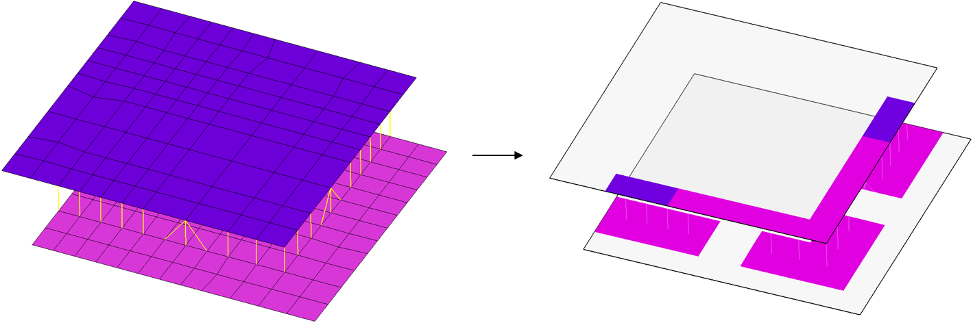
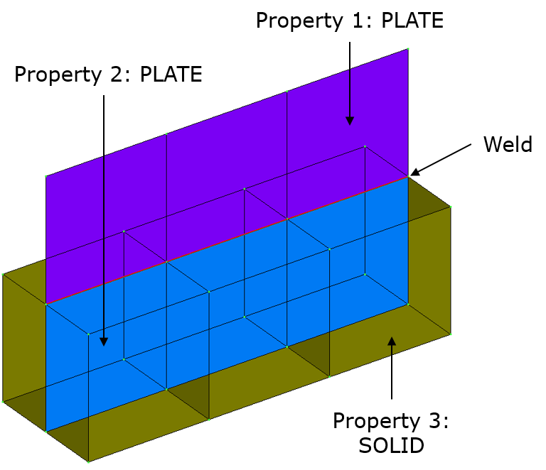
Specifics Of Modelling PLATE/SOLID-Connections
Welds that are intended to be between PLATE- and SOLID-elements need to be modelled in a certain way, so that bending moments can be transmitted correctly. WeldFEM is able to detect those PLATE/SOLID-connections, when meshed properly. For example, along the weld, the PLATE-elements can be extended by one row of elements in the direction of the SOLID-elements. Each PLATE-element of this new row is congruently with the surface of its adjacent SOLID-element. Nodes of PLATE- and SOLID-elements must be merged. The PLATE/SOLID-connection has now additionally become a PLATE/PLATE-connection, which can be detected by WeldFEM.
|
|
|
|
|
|
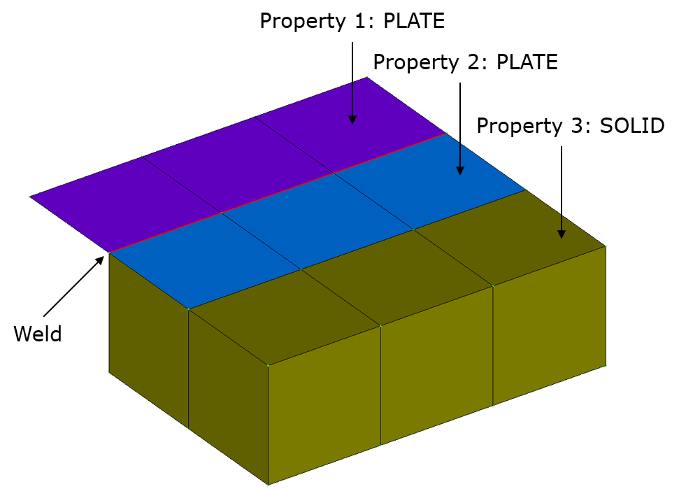
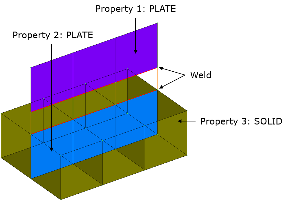
To make sure the weld gets detected, the additional row of PLATE-elements needs to be of a new PLATE-property. This is specially the case in the examples shown above, since these new PLATE/PLATE-connections are technically butt joints and would not get detected by WeldFEM when using the same element property and merged directly by their nodes. There are also other meshing techniques which would result in an additional PLATE/PLATE-connection getting detected as other joint types. Depending on how the connection of both element types is meshed, different joint types could be detected by WeldFEM. In order to set a specified joint type a respective coding notation has been implemented, which is described in
When And Why To Use Coding Notation.
Weld Assessment of Solids
For the weld assessment of 3D-Solid-elements layers of very thin plate elements - referred to as stress gauge elements in the following - can be modelled on top of 3D-solid elements which are in the neighbourhood of weld seams. The stress gauge elements must use the same nodes as the 3D-solid elements faces. It is recommended to supply several rows of stress gauge elements in a range of at least 5 times the prospective weld thickness perpendicular to the weld in order to provide sufficient result points for the assessment procedures. The stress gauge elements are applied to pick up the stresses at the faces of 3D-Solid-elements while not affecting the stiffness of the underlying structure. The thickness has therefore to be below 1.0 mm, e.g. 0.1 mm. This ensured, they will automatically be recognised in WeldFEM. The materials of the stress gauge element properties are recommended to be identical with the underlying 3D-solid element properties. Otherwise deviating stress values would result.
Modelling Welds Not Recommended
In case welds are not modelled WeldFEM compliant, it might not detect the whole weld correctly. Therefore WeldFEM is only able to plot results at locations where a weld has been detected, just like shown below. For this reason it is advised to follow the meshing instructions as described above.