Weld Editor GUI for Eurocode 3
The GUI for the Weld Editor for Eurocode 3 assessments, as shown below, is divided into four sections: Table Of Detected Welds, Assessment Parameters, Highlight Welds and Plot Results.
.PNG)
In this section a table with all detected welds, their labels, corresponding Assessment Parameters as well as the maximum utilisation factor is to be found. Comments, given by the user to self created welds, can be found in the right most column.
The current status of each weld is depicted by the icon in front of the label as described in Weld Editor GUI.
The welds label is composed the in following way:
"Joint Type|Weld Type|Cross-Section|Thickness Of Plate 1 - Thickness Of Plate 2|Notch Case Value ΔσC|Specific Fatigue Resistance Factor γMf|Specific Fatigue Resistance Factor γFf|Weld Material"
There are six different joint types WeldFEM is able to detect:
- B → Butt joint
- C → Corner joint
- O → Overlapped joint
- S → Skew joint
- T → Tee joint
- U → "Universal" joint
Note: γMf and γFf are partial safety factors for Eurocode 3.
Note: "Universal" joints are joint types that WeldFEM could not assign unquestionably. Therefore it is recommended to reassign the "Universal" joints to their actual joint type using the Reassign command described in Weld Manager GUI. A first guess for the joint type is the neighbouring joint type.
Example: C|a|3.5|5.0-5.0|90.0|1.35|1.00|S235J
A fillet weld at a corner joint with an effective cross-section value of 3,5 mm. Both of the welded plates have a thickness of 5 mm. The parameter γMf is 1,35 while γFf is 1,00. The notch case value ΔσC is 90 MPa. The joint plates are made out of S235J.
Note: The colour of the value for the maximum utilisation factor Umax, shown in the respective column, is dependent of the value itself.
A low stress level is indicated by a green colour, which is used for values of Umax < 0,3.
A medium stress level is indicated by a blue colour, which is used for values of 0,3 < Umax < 0,6.
A high stress level is indicated by an orange colour, which is used for values of 0,6 < Umax < 1.
An overloaded weld is indicated by a red colour, which is used for values 1 < Umax.
In this section the Assessment Parameters are specified which will affect the results for each weld.
For changing any parameters the particular weld has to be selected in the table on the left-hand side.
In total six different Assessment Parameters can be specified: Weld Type, User Defined Cross-Section Value [mm], Notch Case Value ΔσC, Specific Fatigue Resistance Factor γMf, Specific Fatigue Resistance Factor γFf and Weld Material.
Weld Type
Selection of a specific weld type which corresponds to its joint type.
Note: WeldFEM will automatically offer weld types which correspond to the detected joint type in the first place. If WeldFEM does not recognize the joint type correctly and thus also the weld type, it is still possible to set up a Weld Type which does not correspond to the detected joint type. This is realised by selecting more in the drop-down-menu.
User Defined Cross-Section Value [mm]
Altering the cross-section value in millimetres for the weld. In case this value is to low or high, WeldFEM will revise it to its closest boundary value.
Note:  is a tool for optimizing the weld cross-section value. It will minimise the weld cross-section value within standard dependent limits, so that the highest utilisation factor for the weld is close to 1.00. This tool is available after calculating the utilisation factors for the first time.
Notch Case Value ΔσC
Selection of the characteristic fatigue resitance value for normal stresses of a specific notch case. It is defined as the fatigue strength value for 2x10⁶ load cycles.
Note: The different notch case values can be found in the tables of appendix B (DIN EN 1993-1-9:2010-12).
Notch Case Value ΔτC
Selection of the characteristic fatigue resitance value for shear stresses. It is defined as the fatigue strength value for 2x10⁶ load cycles.
Note: The notch case value ΔτC is derived by dividing the value ΔσC by the square of 3.
Specific Fatigue Partial Safety Factor γMf
Selection of the specific fatigue partial safety factor, which depends on the design concept and the consequences of component failure.
Specific Fatigue Partial Safety Factor γFf
Selection of the specific fatigue partial safety factor for damage equivalent stress ranges.
Weld Material
Selection of a weld specific material, in case it differs from the parent material.
Design State
Changes the status icon of the weld. It's not a parameter, but rather an indicator for signalling which welds have already been edited and which of them are in their conclusive state.
Note: WeldFEM will automatically swap the Design State from Default to Changed as soon as changes to the weld have been defined.
Once a weld has reached its final editing state, the Design State can be set manually to Consistent (e.g. with the manufacture drawing) for a better overview in the weld table.
Apply For Active Weld
Transfers the current Assessment Parameters settings to the active weld.
Delete Selected Weld
Removes the active from the assessment.
This section offers two different highlight methods to visualise welds and weld-groups in the actual FE-model.
Weld
Highlights the active weld (1D-line-elements representing the weld will be highlighted).
Group
Highlights the group of plate elements which are used to assess the active weld.
Example: Tee joint (no highlighting) 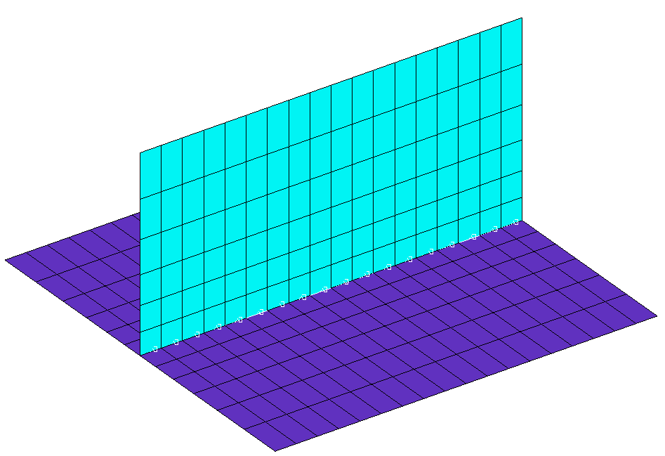
Tee joint (weld highlighted) 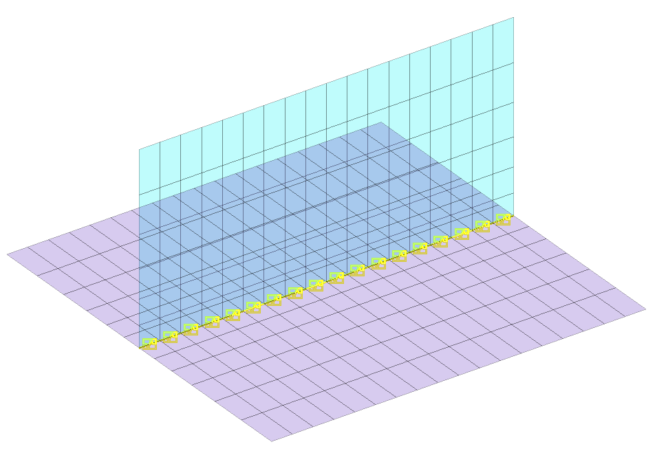
Tee joint (group highlighted) 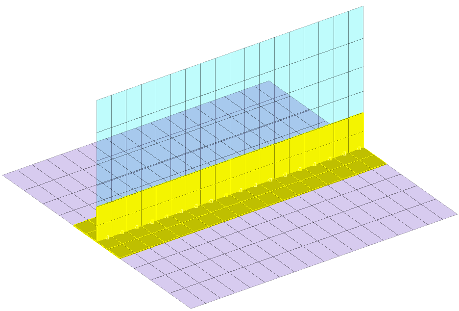
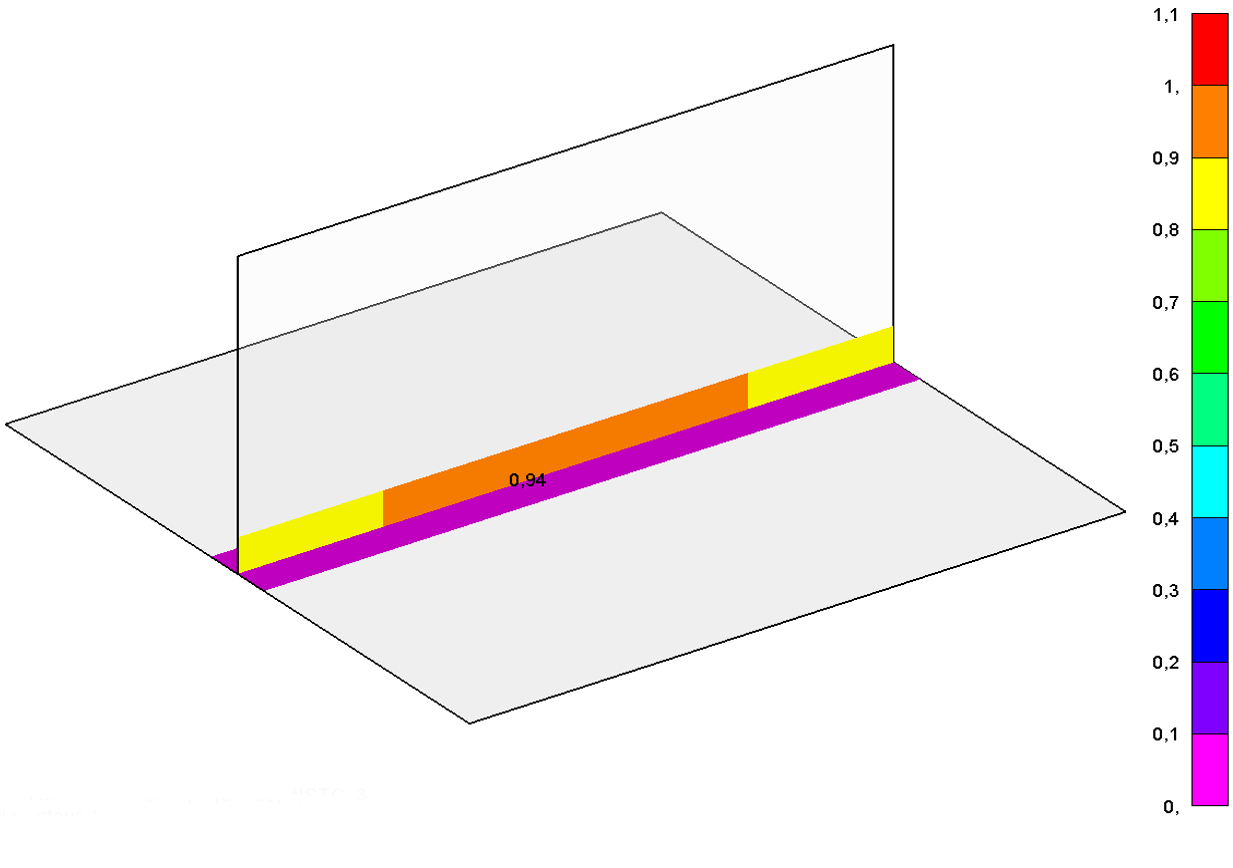
This section offers two functions to visualise the assessment results for either the static assessment or the fatigue assessment in the actual FE-model.
STC
Displays the results for the static assessment of the active weld.
FAT
Displays the results for the fatigue assessment of the active weld.
Note: The way the results are displayed depends on the settings that have been made in the Weld-Detection-GUI (see Weld-Detection GUI).
For Eurocode 3 WeldFEM chooses settings that cannot be changed.
Example: Tee joint (no result plot requested)
Tee joint (STC-Results/FAT-Results)