Calculation Of The Stress Ratio
The stress ratio R is one of the parameters that influence the fatigue strength values of a material. WeldFEM accounts for the reduction of the fatigue strength value due to a certain stress ratios.
Calculation Of The Stress Ratio For Fatigue Assessments According To DVS 1608/DVS 1612
The assessment of the fatigue behaviour of welded structures according to DVS 1608 and DVS 1612 is based on stress values. Therefore, WeldFEM expects its calculation input to be stress values not stress range values. By setting up multiple load cases in the FEA software that represent specific load scenarios, WeldFEM is able to calculate the stress ratio afterwards. The stress ratio for the stresses transformed into the weld coordinate system is calculated for every element of concern regarding all load cases chosen by the user. Thus, the influence of the stress ratio is taken into account for every element of concern separately. Since the time path of the loads is not known, WeldFEM calculates the stress ratio for an element with the overall maximum and minimum stress acting in it. In the following, the calculation of the stress ratio is carried out exemplary for both sides of the CQUAD4-element. The FE-model used for this example has been loaded with service loads according to EN 12663.
Step 1) Gathering All Transformed Stress Components
The transformed stress components of both sides of the CQUAD4-element of concern are summarized in the following table:
|
Load case |
TOP side |
BOT side |
||||
|
σ⊥ [MPa] |
σ|| [MPa] |
τ [MPa] |
σ⊥ [MPa] |
σ|| [MPa] |
τ [MPa] |
|
|
1 |
60,07 |
34,32 |
8,83 |
-68,45 |
-32,90 |
-9,50 |
|
2 |
-60,91 |
-33,83 |
-8,57 |
71,10 |
34,90 |
9,45 |
|
3 |
-3,05 |
1,04 |
4,24 |
-0,56 |
1,76 |
5,41 |
|
4 |
2,21 |
-0,55 |
-3,98 |
3,21 |
0,24 |
-5,46 |
|
5 |
-1,26 |
0,74 |
0,39 |
3,98 |
3,00 |
-0,07 |
|
6 |
0,42 |
-0,25 |
-0,13 |
-1,33 |
-1,00 |
0,02 |
Step 2) Extracting The Maximum And Minimum Stress Values
The maximum and minimum stress values of the element of concern are summarized in the following table:
|
Extreme values |
TOP side |
BOT side |
||||
|
σ⊥ |
σ|| |
τ |
σ⊥ |
σ|| |
τ |
|
|
min |
-60,91 |
-33,83 |
-8,57 |
-68,45 |
-32,90 |
-9,50 |
|
max |
60,07 |
34,32 |
8,83 |
71,10 |
34,90 |
9,45 |
Step 3) Calculating The Stress Ratio
In the DVS 1608 and DVS 1612 the allowable fatigue strength values are given in the MKJ-curves for the tension and compression range separately. The calculation of the stress ratio is calculated differently for the tension and compression range, as depicted in the following figure.
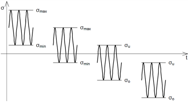
For the tension range the stress ratio for normal stresses is decisive and can be calculated by following formula: 
For the compression range the reciprocal value of the stress ratio for normal stresses is decisive and can be calculated by following formula: 
For the tension or compression range the stress ratio for shear stresses is decisive and can be calculated by following formula: 
|
Stress ratio |
TOP side |
BOT side |
||||
|
σ⊥ |
σ|| |
τ |
σ⊥ |
σ|| |
τ |
|
|
R |
- |
0,986 |
0,971 |
0,963 |
0,943 |
0,995 |
|
κ |
0,986 |
- |
- |
- |
- |
- |
As can be seen above, the stress ratio R depends fully on the load cases that have been chosen for the fatigue assessment.
Calculation Of The Stress Ratio For Fatigue Assessments According To Eurocode 3/EN 13001-3-1
The assessment of the fatigue behaviour of welded structures according to Eurocode 3 and EN 13001-3-1 is based on stress range values. Therefore, WeldFEM expects its calculation input to be stress range values not plain stress values. In WeldFEM itself there are two options to assess structures with stress range values. One is without the selection and one is with the selection of a reference load case. These two options will be explained in the following exemplary.
Option 1) Calculation without a reference load case
The first option corresponds to the assessment without the choice of a reference load case. Here FE-results need to represent stress range values. With the FE-results representing stress range values, WeldFEM cannot calculate any stress ratio. And since the time path of the loads is not known, WeldFEM assumes a stress ratio of R = 0, as shown in the figure below. This means the stress value extracted from the FE-results  is taken directly as the decisive stress range value
  .
.
.PNG)
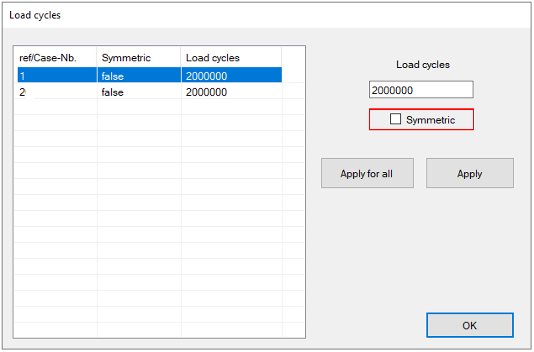
When setting up the load cycles for the weld assessment the additional setting Symmetric can be chosen. This setting is found in the GUI shown below, which pops up during a fatigue assessment initiated by Process StressData in the Main GUI.
Enabling the setting Symmetric when calculating without a reference load case leads to a change of two parameters, the stress range value and the stress ratio.
The extracted stress range values are doubled, thus rendering a stress ratio of R = -1. These circumstances are depicted in the figures below.
Here it can be seen how the stress range value is now calculated using the stress value from the FE-results and the stress value derived from the FE-results multiplied by -1, thus rendering the stress ratio of R = -1.
|
|
|
|
Symmetric is disabled |
Symmetric is enabled |
.PNG)
Option 2) Calculation with a reference load case
The second option corresponds to the assessment with the choice of a reference load case. Here FE-results need to represent stress values, thus allowing WeldFEM to calculate the stress ratio. The results derived from the reference load case specify the stress value to which the stress ratio is to be determined. This process is depicted in the following figure exemplary. Here three load cases have been chosen for the fatigue assessment, setting up the first one of them, which renders the , as reference load case.
.png)
Enabling the setting Symmetric when calculating with a reference load case also leads to a change of two parameters, the stress range value and the stress ratio.
The calculated stress range values are doubled, thus rendering a new stress ratio that is calculated on basis of the new stress  . These circumstances are depicted in the figures below.
Here it can be seen how the old stress range value  is doubled, rendering the new stress range value. Furthermore, it can be seen how the new stress value is the new low, hence making it decisive when calculating the new stress ratio.
|
|
|
|
Symmetric is disabled |
Symmetric is enabled |
%202.png)
%202.png)
Note: Choosing a reference load case is currently only available for EN 13001-3-1.