Calculation Of The Evaluation Range
The standards included in WeldFEM are based on the nominal stress concept. Therefore, when extracting the stresses using a strain gauge, a certain distance from the seam transition must be maintained. By that the structure and notch-related increase in stress can be excluded. In a FEA, the results usually do not contain nominal stresses, but local stresses. Depending on the used mesh, these can behave like notch stresses, nominal stresses or something in between. Therefore, for the extraction of stress values, the same principle applies as when determining the required stress values using a strain gauge, an evaluation distance is to be applied. In the standards DVS 1608 and DVS 1612 the evaluation range is specified by a distance to the weld toe. There is no evaluation range based on a distance from the weld root. The DIN EN 13001-3-1 does not contain any recommendations for an evaluation using a FEA. Thus the ones from DVS 1612 are adopted, since both standards are based on the nominal stress concept.
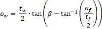
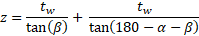
The following equation was defined in WeldFEM to calculate the evaluation range:

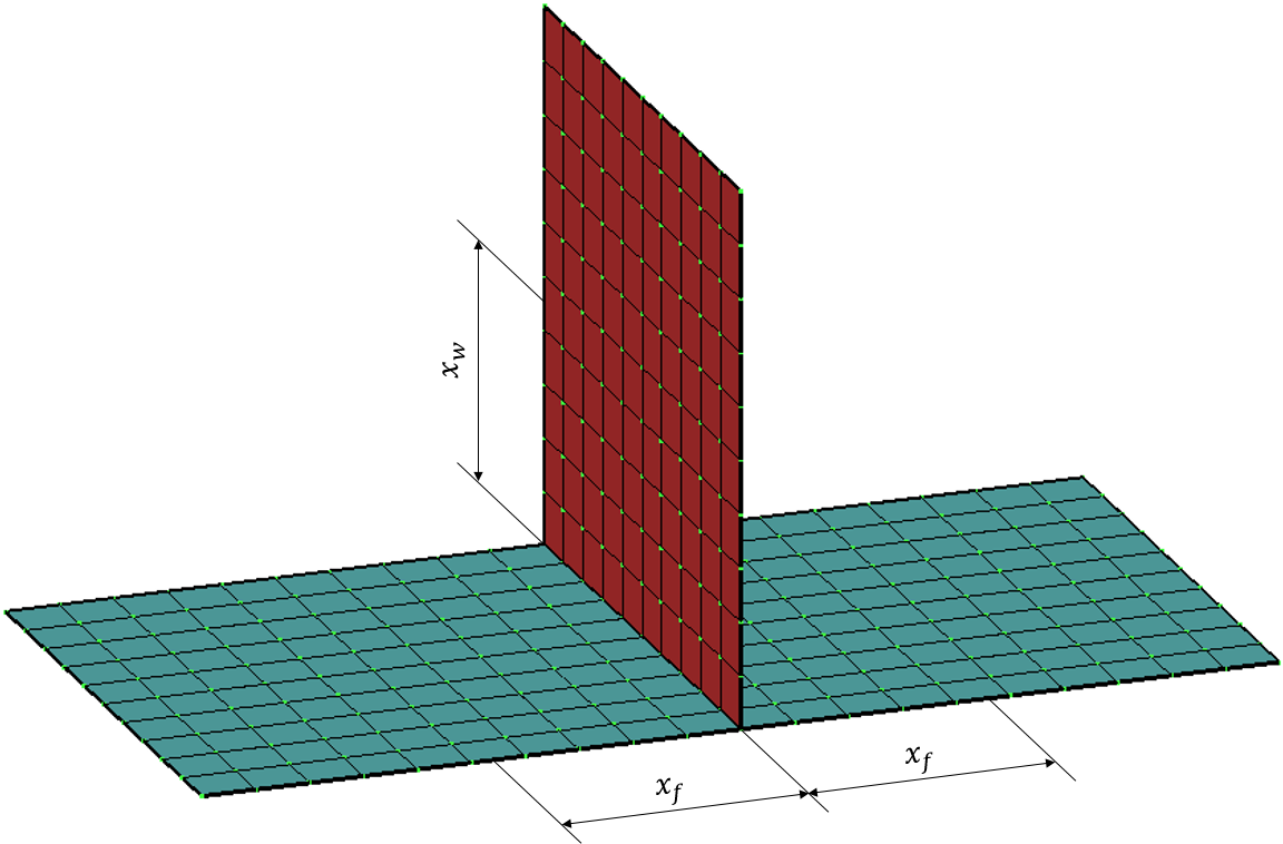
The weld assessment of WeldFEM runs on a FE model which is based on two dimensional shell-elements. No three-dimensional properties can be represented with these. The weld orientation and weld geometry cannot be reproduced in detail. For the implementation of the above equation, assumptions had to be made for certain joint types and weld seam shapes in order to determine a reasonable evaluation distance. The term “Standard Specification” can be found in the relevant literature. The “Offset” and the “Weld Leg Length” are values determined by the weld geometry. These are shown in retrospect for the different types of joints and seam shapes.
|
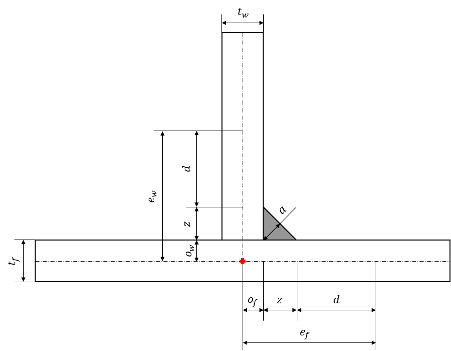
Tee Joint |
|
|
Fillet Weld / Z Fillet Weld |
|
|
Weld geometry: |
FE-adaptation: |
|
|
|
|
Formula:
Note: The cross section of the weld |
Formula: Note: The adapted evaluation range for the flange of the FE-model Note: The offset |
|
|
|
|
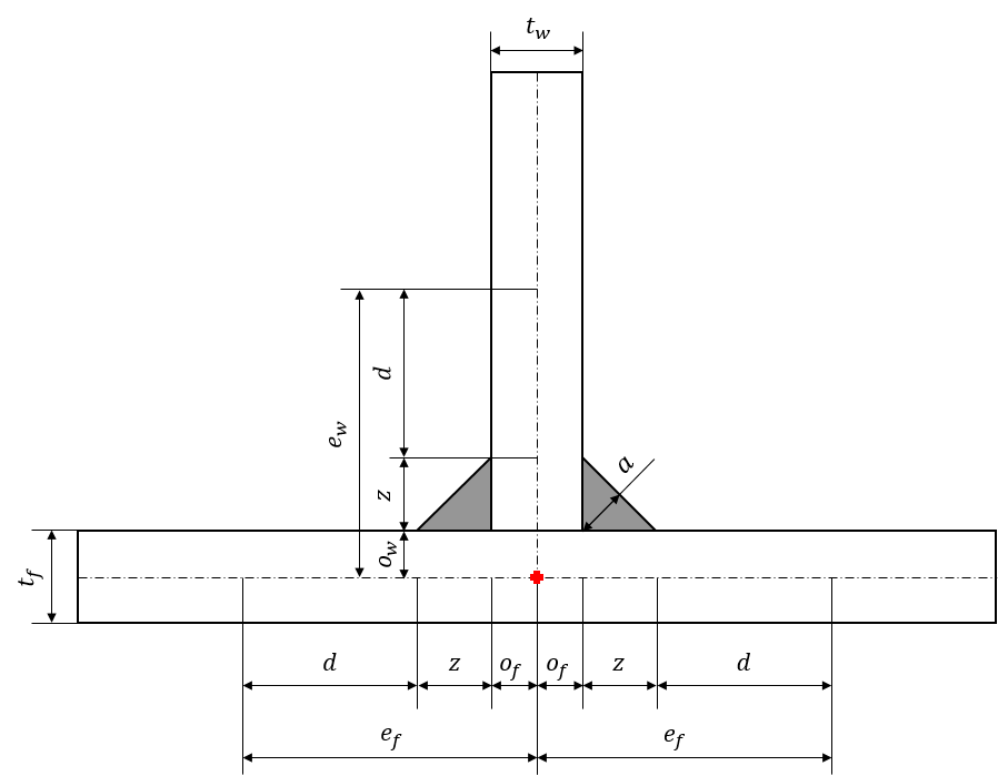
Double Fillet Weld |
|
|
Weld geometry: |
FE-adaptation: |
|
|
|
|
Formula:
Note: The cross section of the weld |
Formula: Note: The adapted evaluation range for the flange Note: The offset |
|
|
|
|
HY Weld |
|
|
Weld geometry: |
FE-adaptation: |
|
|
|
|
Formula:
Note: The factor of the root face size |
Formula: Note: The adapted evaluation range for the flange Note: For the calculation of Note: The offset |
|
|
|
|
HV Weld |
|
|
Weld geometry: |
FE-adaptation: |
|
|
|
|
Formula:
Note: The size of the root face size |
Formula: Note: The adapted evaluation range for the flange Note: For the calculation of Note: The offset |
|
|
|
|
Corner Joint |
|
|
Fillet Weld / Z Fillet Weld |
|
|
Weld geometry: |
FE-adaptation: |
|
|
|
|
Formula:
|
Formula: Note: The offset |
|
|
|
|
Z Fillet Weld with sealing run |
|
|
Weld geometry: |
FE-adaptation: |
|
|
|
|
Formula:
|
Formula: Note: The offset Note: |
|
|
|
|
Butt Joint |
|
|
HY Weld |
|
|
Weld geometry: |
FE-adaptation: |
|
|
|
|
Formula:
Note: The factor of the root face size |
Formula: Note: For the calculation of Note: The weld leg length will be added to both evaluation ranges, |
|
|
|
|
HV Weld |
|
|
Weld geometry: |
FE-adaptation: |
|
|
|
|
Formula:
Note: The size of the root face size |
Formula: Note: For the calculation of Note: The weld leg length will be added to both evaluation ranges, |
|
|
|
|
Y Weld |
|
|
Weld geometry: |
FE-adaptation: |
|
|
|
|
Formula:
Note: The factor of the root face size |
Formula: Note: For the calculation of Note: The asymmetry of the HY weld would lead to a evaluation range with a larger value than the one from the Y weld, since the orientation of the weld is unknown and therefore the weld leg length is added on both sides. This could potentially lead to better results with the HY weld, because elements farther away from the weld would have been taken into account when assessing the weld. In order to treat the HY and the Y weld in terms of the evaluation range equally, the angle of aperture |
|
|
|
|
V Weld |
|
|
Weld geometry: |
FE-adaptation: |
|
|
|
|
Formula:
Note: The size of the root face size |
Formula: Note: For the calculation of Note: The asymmetry of the HY weld would lead to a evaluation range with a larger value than the one from the Y weld, since the orientation of the weld is unknown and therefore the weld leg length is added on both sides. This could potentially lead to better results with the HY weld, because elements farther away from the weld would have been taken into account when assessing the weld. In order to treat the HY and the Y weld in terms of the evaluation range equally, the angle of aperture |
|
|
|
|
I Weld |
|
|
Weld geometry: |
FE-adaptation: |
|
|
|
|
Formula:
Note: The size of the root opening |
Formula: Note: For the calculation of |
|
|
|
|
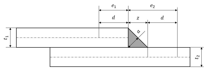
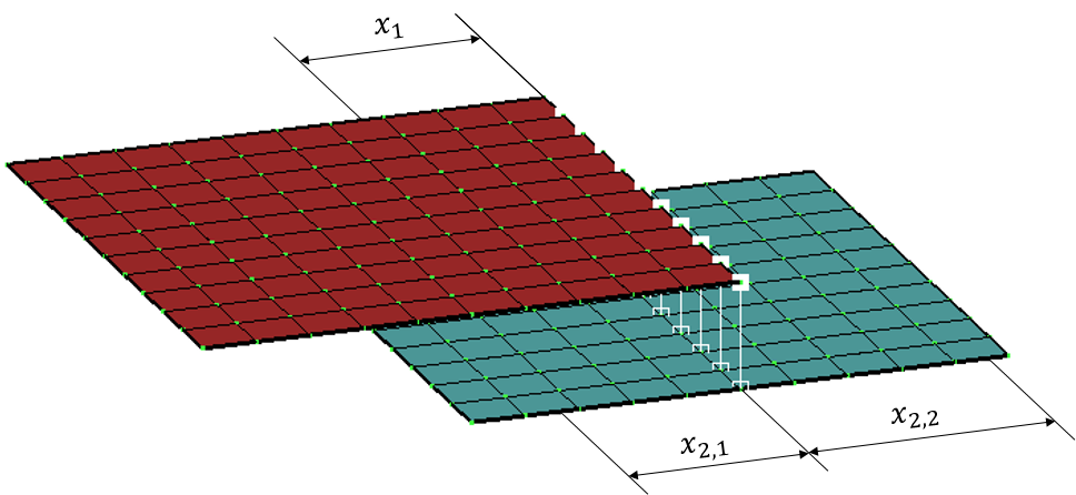
Overlap Joint |
|
|
Z Fillet Weld |
|
|
Weld geometry: |
FE-adaptation: |
|
|
|
|
Formula:
Note: The cross section of the weld |
Formula: Note: The evaluation range |
|
|
|
|
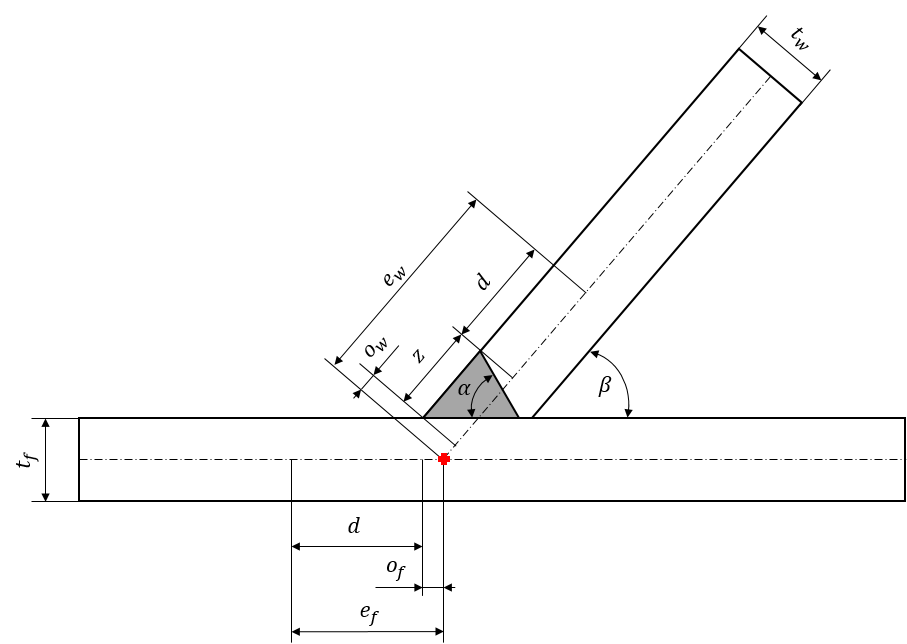
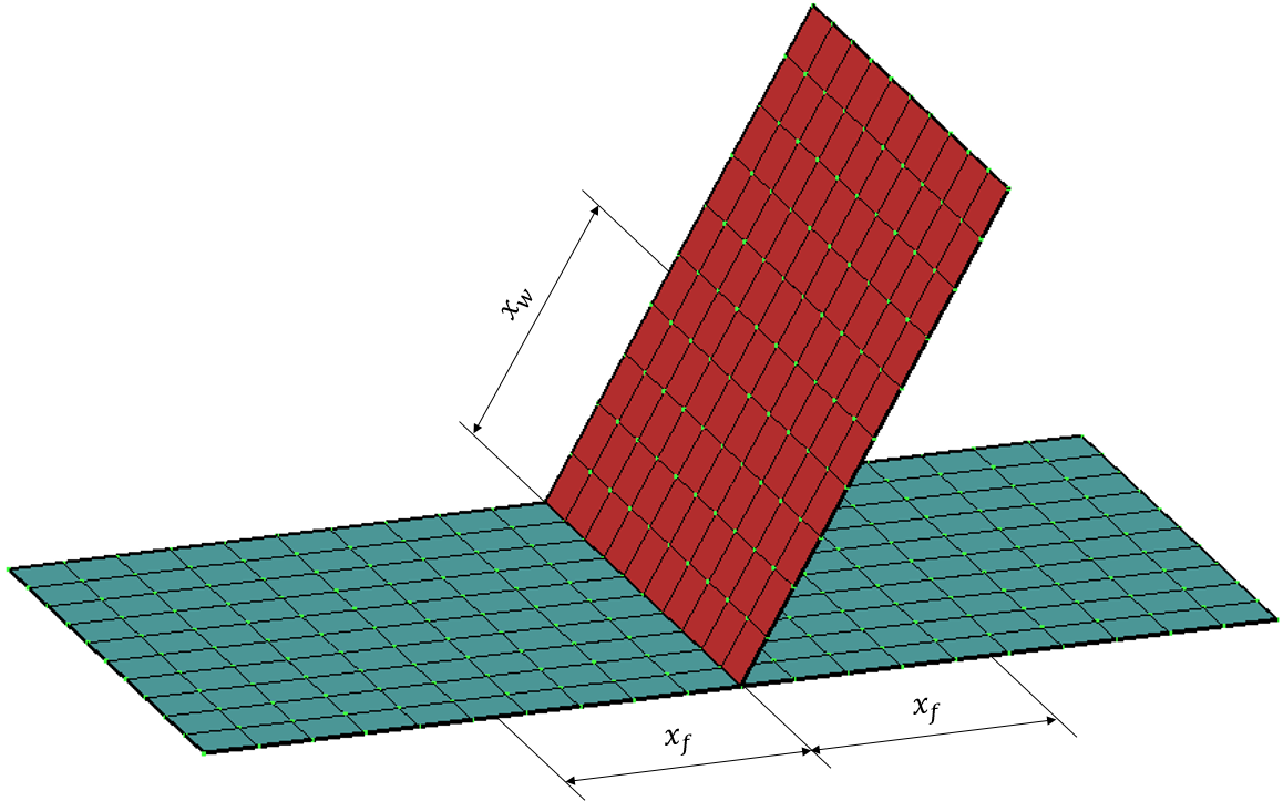
Skew Joint |
|
|
HY Weld |
|
|
Weld geometry: |
FE-adaptation: |
|
|
|
|
Formula:
Note: The angle of aperture |
Formula: Note: The adapted evaluation range for the flange of the FE-model Note: The weld leg length Note: The calculation of the offsets for the FE-adaptation will be simplified as followed for skew joints. |
|
|
|
|
HV Weld |
|
|
Weld geometry: |
FE-adaptation: |
|
|
|
|
Formula:
Note: The angle of aperture |
Formula: Note: The adapted evaluation range for the flange of the FE-model Note: The weld leg length Note: The calculation of the offsets for the FE-adaptation will be simplified as followed for skew joints. |