Calculation Of The Allowable Stress Values For Weld Joints
The allowable stress values that are used to determine the utilisation factors in general need to be calculated, depending on the thicknesses of the connected sheets, the stress ratio, the weld material and the assessment standard. WeldFEM does these calculations using the information given in the settings and the FE-model.
Example: The allowable stress values for a fatigue assessment according to DVS 1612 are to be calculated for a tee joint, realised as one sided fillet weld. The weld material is S355J. The thickness of both sheets is 12,5 mm.
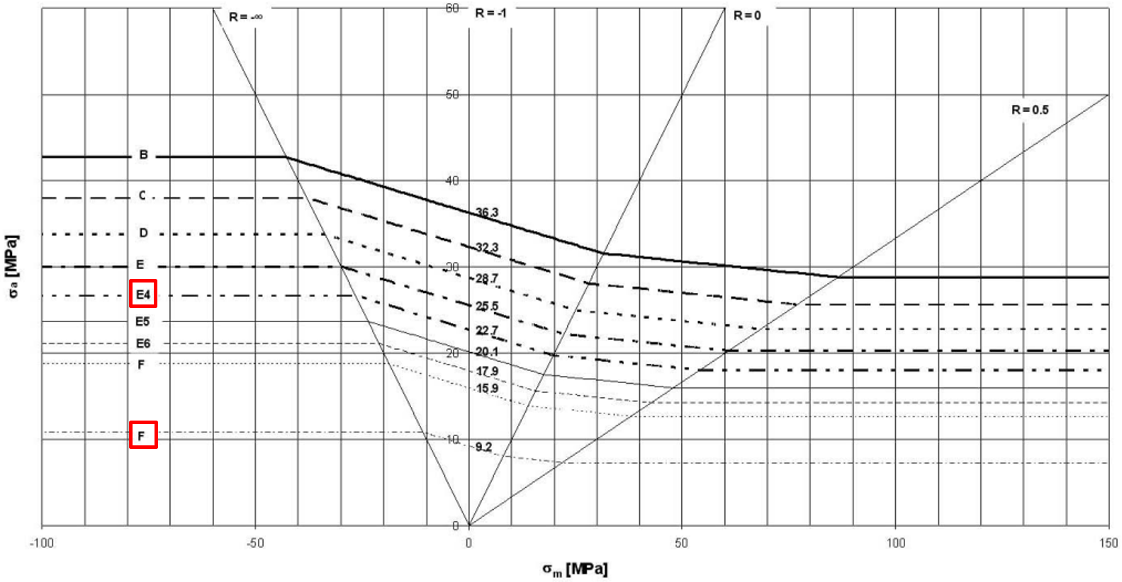
Step 1) The first step includes defining the MKJ-curves which match the notch case. For the fillet weld the most conservative MKJ-curves for the perpendicular normal stress component is F3 and for the parallel normal stress component E4. The shear stress MKJ-curve is H-.
The corresponding exponent x of the selected MKJ-curves for normal stress are x = 41 for F3 and x = 18 for E4.
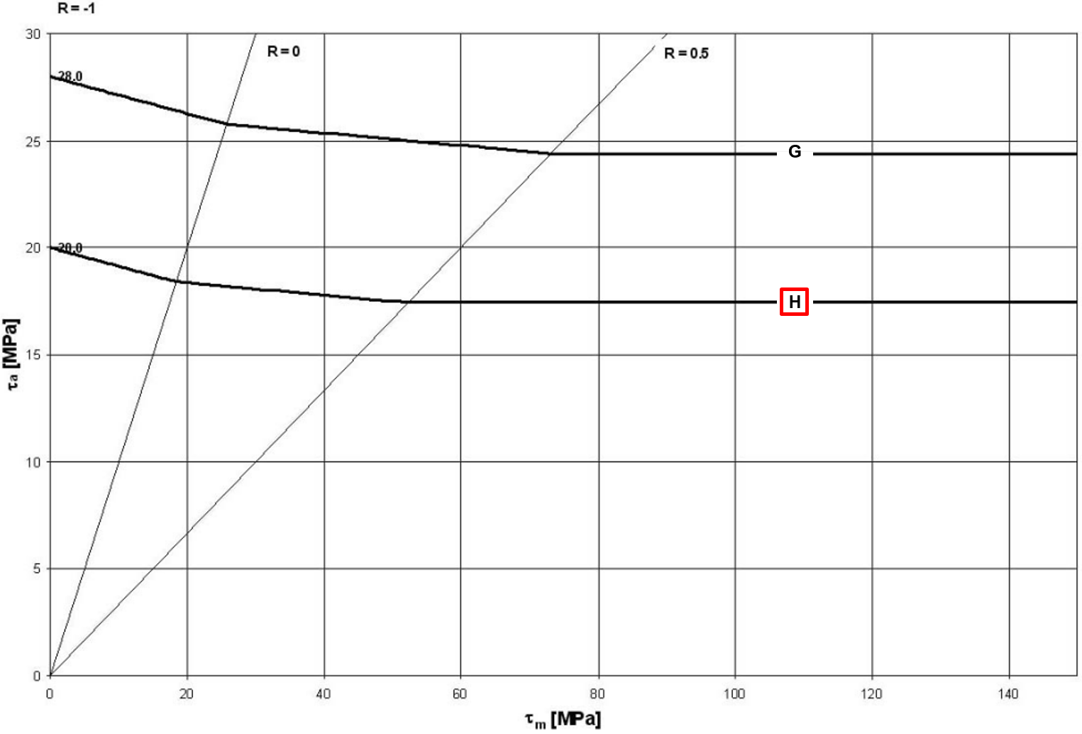
The maximum allowable stress shear for a stress ratio of R = -1 is τzul, R=-1 = 53 MPa.
The MKJ-curves used are shown below. The graphs were taken directly from the DVS 1612.
.PNG)
 (bearbeitet).PNG)
Step 2) The second step includes determining the maximum and minimum stress values, in order to calculate the stress ratio. For the purpose of this example a stress ratio of Rσ=Rτ=-0,7 will be assumed. Note that this has to be determined for every weld element and over all selected load cases.
Step 3) The third steps includes calculating the allowable stress values for normal and shear stress components according to the formula given in the DVS 1612.
The allowable normal stress value can be calculated by following formula: ![]()
The allowable shear stress value can be calculated by following formula: ![]()
According to the given information about the weld and formula the allowable stress values are σ⊥,zul = 32,90 MPa, σ||,zul = 81,08 MPa and τzul = 59,63 MPa.
Step 4) Since both of the sheets posses a thickness greater than 10 mm, the allowable stress values calculated beforehand need to be down scaled according to the following formula: ![]()
This formula can be used analogously for σ⊥,zul and τzul.
Therefore the new allowable stress values are σ⊥,zul = 32,17 MPa, σ||,zul = 79,29 MPa and τzul = 58,32 MPa.
Example: The allowable stress values for a fatigue assessment according to DVS 1608 are to be calculated for a tee joint, realised as one sided fillet weld. The weld material is EN AW 6060. The thickness of both sheets is 12,5 mm.
Step 1) The first step includes defining the MKJ-curves which match the notch case. For the fillet weld the most conservative MKJ-curves for the perpendicular normal stress component is F2 and for the parallel normal stress component E4. The shear stress MKJ-curve is H.
The corresponding exponent x of the selected MKJ-curves for normal stress are x = 41 for F2 and x = 18 for E4.
The corresponding exponent x of the selected MKJ-curves for shear stress is x = 9 for H.
The MKJ-curves and Haigh-diagrams used are shown below. The graphs were taken directly from the DVS 1608.
.png)
.png)
Step 2) The second step includes determining the maximum and minimum stress values, in order to calculate the stress ratio. For the purpose of this example a general stress ratio of Rσ=Rτ=-0,7 will be assumed. Note that this has to be determined for every weld element and over all selected load cases.
Step 3) The third steps includes calculating the allowable stress values for normal and shear stress components according to the formula given in the DVS 1608.
The allowable normal stress value can be calculated by following formula: 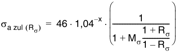
The allowable shear stress value can be calculated by following formula: 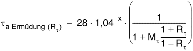
With Mσ = 0,15 and Mτ = 0,09 (Mean stress sensitivity specified by DVS 1608) the allowable stress values are σ⊥,zul = 8,98 MPa, σ||,zul = 22,12 MPa and τzul = 19,35 MPa.
Step 4) Since both of the sheets posses a thickness greater than 10 mm, the allowable stress values calculated beforehand need to be down scaled according to the following formulas: ![]() ,
, ![]() , with
, with ![]() .
.
Therefore the new allowable stress values are σ⊥,zul = 8,78 MPa, σ||,zul = 21,63 MPa and τzul = 18,92 MPa.
Example: The allowable stress values for a fatigue assessment according to DIN EN 13001-3-1 are to be calculated for a tee joint, realised as double fillet weld. The weld material is S355J. The thickness of both sheets is 12,5 mm. It is also known that it is not a fail-safe component and may pose a risk to people. In addition, good accessibility of the weld seam is not guaranteed. The reference number of cycle Nref is equal to 2*106, while the total number of cycles Nt is equal to 1,5*106.
Additional the following table with information regarding present load ranges of one weld element is given:
|
|
|
|
1 |
50 |
25 |
100.000 |
2 |
40 |
20 |
200.000 |
3 |
30 |
15 |
400.000 |
4 |
20 |
10 |
800.000 |


Note that the calculation steps performed here have to be done for all weld elements.
Step 1) In the first step the factor γmf can be derived from the information given. According to table 9 in DIN EN 13001-3-1 the factor γmf is equal to 1,25.
Step 2) The second step includes defining the allowable load range value Δσc and Δτc and the inverse Wöhler exponent m according to the notch cases given in the appendix D of the DIN EN 13001-3-1.
For the double fillet weld a load range value of Δσc = Δτc = 63 MPa can be used. The value for the inverse Wöhler exponent is m = 3.
A picture showing the notch case is given below. The shown section of the table is taken directly from the appendix D of DIN EN 13001-3-1.
.PNG)
Step 3) The third step includes calculating the stress progression parameter sm according to the following formula: ![]()
The relative total number of occurrences of load ranges ν can be calculated by following formula: ![]()
The stress collective coefficient km can be calculated by following formula: ![]()
According to the given information about the weld and formula the values of these parameters are ν = 0,75, km = 0,227.
Therefore the stress progression parameter is sm = 0,1703
Step 4) The fourth steps includes calculating the allowable stress range values for normal and shear stress components.
The allowable normal stress range can be calculated with the following formula: ![]()
The same procedure is used for the allowable shear stress range.
According to the given formula the allowable stress range values for that one specific weld element are ΔσRd = 90,93 MPa and ΔτRd = 90,93 MPa.