Calculation Of The Allowable Fatigue Values For Weld Joints
The allowable stress values that are used to determine the utilisation factors in general need to be calculated, depending on the thicknesses of the connected sheets, the stress ratio, the weld material and the assessment standard. WeldFEM conducts these calculations using the information given in the settings and the FE-model.
The particular steps for the calculations are explained for a distinct example for comprehensibility in the following.
Allowable Fatigue Stress Values For DVS 1612
The allowable stress values for a fatigue assessment according to DVS 1612 are to be calculated for a tee joint, realised as one sided fillet weld. The weld material is S355J. The thickness of both sheets is 12,5 mm.
Step 1) Select MKJ-Curves
The first step includes defining the MKJ-curves which match the notch case. For the fillet weld the most conservative MKJ-curves for the perpendicular normal stress component is F3 and for the parallel normal stress component E4. The shear stress MKJ-curve is H-.
The corresponding exponent x of the selected MKJ-curves for normal stress are x = 41 for F3 and x = 18 for E4.
The maximum allowable stress shear for a stress ratio of R = -1 is τzul, R=-1 = 53 MPa.
The MKJ-curves used are shown below. The graphs were taken directly from the DVS 1612.
.PNG)
%20(bearbeitet).PNG)
Step 2) Determine The Stress Ratio
The second step includes determining the maximum and minimum stress values, in order to calculate the stress ratio. For the purpose of this example a stress ratio of Rσ=Rτ=-0,7 will be assumed. Note that this has to be determined for every weld element and over all selected load cases.
Step 3) Calculate The Allowable Stresses
The third steps includes calculating the allowable stress values for normal and shear stress components according to the formula given in the DVS 1612.
The allowable normal stress value can be calculated by following formula: 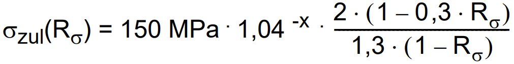
The allowable shear stress value can be calculated by following formula: 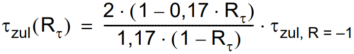
According to the given information about the weld and formula the allowable stress values are σ⊥,zul = 32,90 MPa, σ||,zul = 81,08 MPa and τzul = 59,63 MPa.
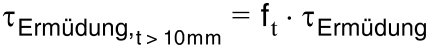
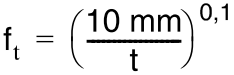
Step 4) Consideration Of The Sheet Thickness Influence
Since both of the sheets posses a thickness greater than 10 mm, the allowable stress values calculated beforehand need to be down scaled.
This is done according to the following formula: 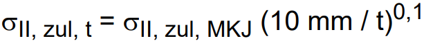
The formula can be used analogously for σ⊥,zul and τzul.
Therefore the new allowable stress values are σ⊥,zul = 32,17 MPa, σ||,zul = 79,29 MPa and τzul = 58,32 MPa.
Allowable Fatigue Stress Values For DVS 1608
The allowable stress values for a fatigue assessment according to DVS 1608 are to be calculated for a tee joint, realised as one sided fillet weld. The weld material is EN AW 6060. The thickness of both sheets is 12,5 mm.
Step 1) Select MKJ-Curves
The first step includes defining the MKJ-curves which match the notch case. For the fillet weld the most conservative MKJ-curves for the perpendicular normal stress component is F2 and for the parallel normal stress component E4. The shear stress MKJ-curve is H.
The corresponding exponent x of the selected MKJ-curves for normal stress are x = 41 for F2 and x = 18 for E4.
The corresponding exponent x of the selected MKJ-curves for shear stress is x = 9 for H.
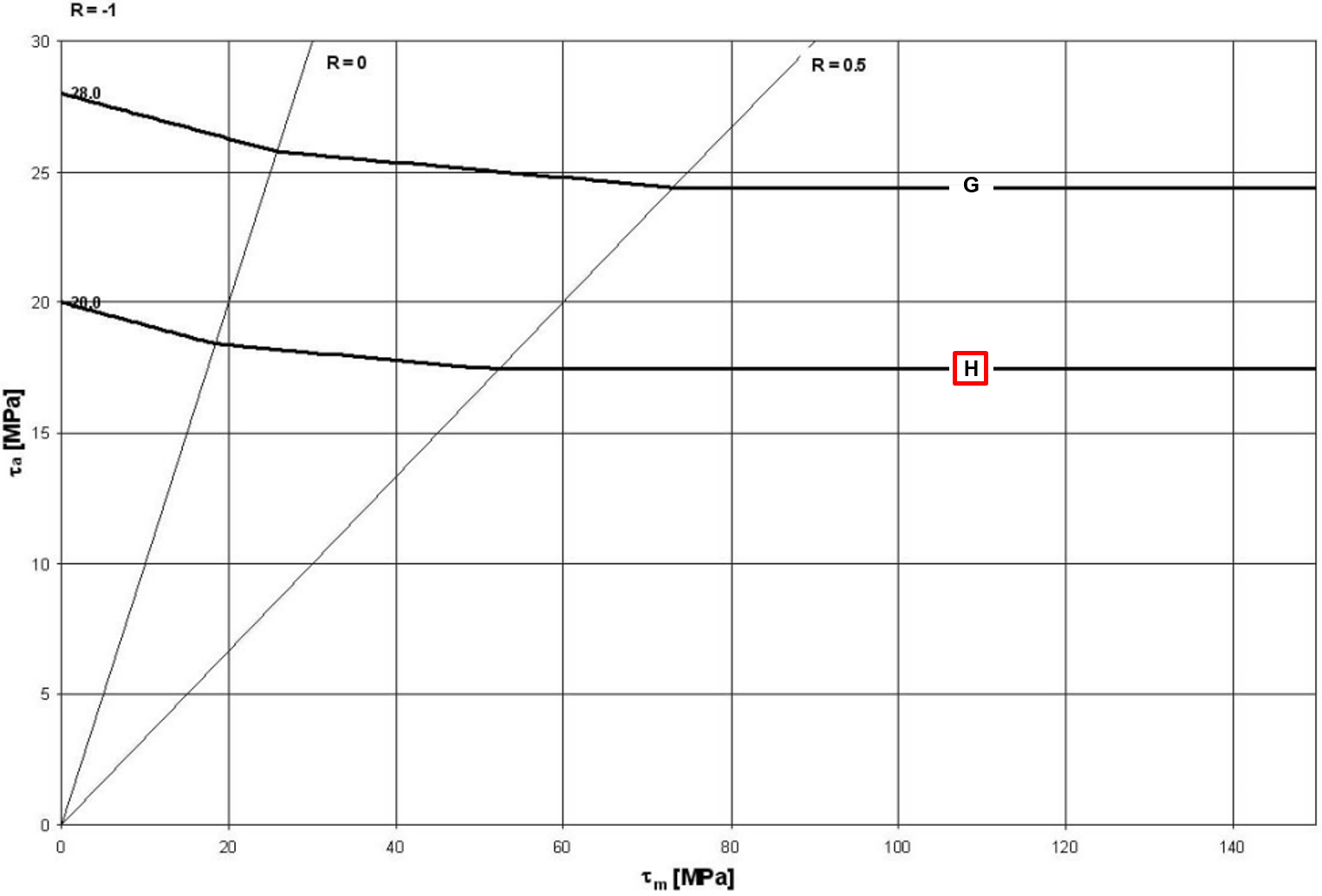
The MKJ-curves and Haigh-diagrams used are shown below. The graphs were taken directly from the DVS 1608.
.png)
.png)
Step 2) Determine The Stress Ratio
The second step includes determining the maximum and minimum stress values, in order to calculate the stress ratio. For the purpose of this example a general stress ratio of Rσ=Rτ=-0,7 will be assumed. Note that this has to be determined for every weld element and over all selected load cases.
Step 3) Calculate The Allowable Stresses
The third steps includes calculating the allowable stress values for normal and shear stress components according to the formula given in the DVS 1608.
The allowable normal stress value can be calculated by following formula: 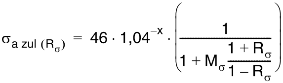
The allowable shear stress value can be calculated by following formula: 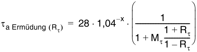
With Mσ = 0,15 and Mτ = 0,09 (Mean stress sensitivity specified by DVS 1608) the allowable stress values are σ⊥,zul = 8,98 MPa, σ||,zul = 22,12 MPa and τzul = 19,35 MPa.
Step 4) Consideration Of The Sheet Thickness Influence
Since both of the sheets posses a thickness greater than 10 mm, the allowable stress values calculated beforehand need to be down scaled.
This is done according to the following formulas: 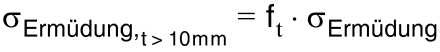 ;
;  ;
;  .
.
Therefore the new allowable stress values are σ⊥,zul = 8,78 MPa, σ||,zul = 21,63 MPa and τzul = 18,92 MPa.
Allowable Fatigue Stress Values For DIN EN 13001-3-1
The allowable stress values for a fatigue assessment according to DIN EN 13001-3-1 are to be calculated for a tee joint, realised as double fillet weld. The weld material is S355J. The thickness of both sheets is 12,5 mm. It is also known that it is not a fail-safe component and may pose a risk to people. In addition, good accessibility of the weld seam is not guaranteed. The reference number of cycle Nref is equal to 2*106, while the total number of cycles Nt is equal to 1,5*106.
Additional the following table with information regarding present load ranges of the highest stressed weld element is given:
|
|
|
|
|
|
1 |
50 |
25 |
100.000 |
|
2 |
40 |
20 |
200.000 |
|
3 |
30 |
15 |
400.000 |
|
4 |
20 |
10 |
800.000 |


Step 1) Selection Of The Coefficient γmf
In the first step the factor γmf can be derived from the information given. According to table 9 in DIN EN 13001-3-1 the factor γmf is equal to 1,25.
Step 2) Selection Of The Notch Case
The second step includes defining the allowable load range value Δσc and Δτc and the inverse Wöhler exponent m according to the notch cases given in the appendix D of the DIN EN 13001-3-1.
For the double fillet weld a load range value of Δσc = Δτc = 63 MPa can be used. The value for the inverse Wöhler exponent is m = 3.
A picture showing the notch case is given below. The shown section of the table is taken directly from the appendix D of DIN EN 13001-3-1.
.PNG)
Step 3) Calculation Of The Parameter sm
The third step includes calculating the stress progression parameter sm according to the following formula: 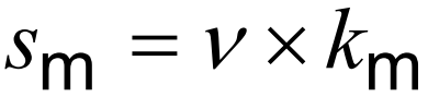
The relative total number of occurrences of load ranges ν can be calculated by following formula: 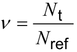
The stress collective coefficient km can be calculated by following formula: 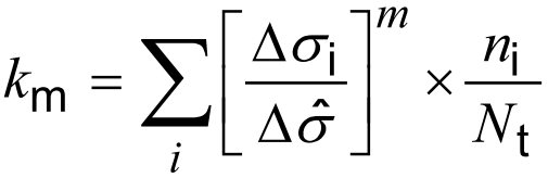
According to the given information about the weld and equations the values of these parameters are ν = 0,75, km = 0,227.
Therefore the stress progression parameter is sm = 0,1703
Step 4) Calculation Of The Allowable Stress Ranges
The fourth steps includes calculating the allowable stress range values for normal and shear stress components.
The allowable normal stress range can be calculated with the following formula: 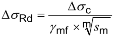
The same procedure is used for the allowable shear stress range.
According to the given formula the allowable stress range values for that one specific weld element are ΔσRd = 90,93 MPa and ΔτRd = 90,93 MPa.
Allowable Numbers Of Load Cycles For Eurocode 3
With Eurocode 3, the fatigue utilisation factor can be calculated in a Palmgreen-Miner scheme as the sum of the partial damages at each stress range level. Therefore, when assessing welds according to Eurocode 3, allowable numbers of load cycles are calculated for each stress range level. This value is then compared with the actual numbers of load cycles each stress range level is acting at.
Note: For the assessment according to Eurocode 3 WeldFEM expects its calculation input to be stress ranges.
The allowable numbers of load cycles for a fatigue assessment according to Eurocode 3 are to be calculated for a tee joint, realised as single fillet weld. The weld itself is loaded and made out of the material is S355J. The thickness of both sheets is 5 mm. It is also known that it is not a damage tolerant component and may pose a high risk if failure occurs. The load cases of concern are not symmetrical.
The maximum stress ranges along the weld are extrapolated structural stresses and have already been upscaled according to the method described in Up Scaling Of The Transformed Stress Values.
The following table with information regarding the highest stressed weld element is given.
|
|
|
|
ni |
|
1 |
80 |
30 |
100.000 |
|
2 |
60 |
20 |
400.000 |
|
3 |
40 |
10 |
1.000.000 |
Step 1) Selection Of Coefficients γFf, γMf And The Notch Case
In the first step the factor γFf and γMf can be derived from the information given. The notch case can be determined in the first step as well.
According to table 3.1 in DIN EN 1993-1-9 the factor γMf is equal to 1,35. The factor γFf is equal to 1,00. The reference value of the fatigue strength at 2 million cycles Δσc can be determined using table B.1 in the appendix B of the DIN EN 1993-1-9. For the weld of concern the value of the fatigue strength at 2 million cycles is equal to 90 MPa, since the relevant notch case is FAT90.
Step 2) Calculation Of Threshold Values For Stress Ranges
The second step consists of calculating the fatigue limit for constant amplitude stress ranges at the number of cycle ND, ΔσD, and the cut-off limit for stress ranges at the number of cycles NL, for normal stress ranges ΔσL as well as for shear stress ranges ΔτL.
The fatigue limit for constant amplitude stress ranges at the number of cycle ND can be calculated by following equation: 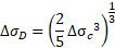
The cut-off limit for normal stress ranges at the number of cycles NL can be calculated by following equation: 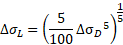
The cut-off limit for shear stress ranges at the number of cycles NL can be calculated by following equation: 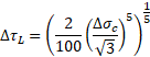
According to the given information about the weld and equations the values of these parameters are ΔσD = 66,31 MPa, ΔσL = 36,42 MPa and ΔτL = 23,76 MPa.
Step 3) Calculation Of Weld Stresses
In the third step the fatigue relevant stresses acting in the weld, the normal stress σwf and the shear stress τwf along the weld, are being calculated.
The normal stress σwf can be calculated by following equation: 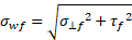
The normal stress σwf can be calculated by following equation: 
This results in the following weld stresses:
|
|
σwf,i [MPa] |
τwf,i [MPa] |
ni |
|
1 |
85,44 |
30 |
100.000 |
|
2 |
63,25 |
20 |
400.000 |
|
3 |
41,23 |
10 |
1.000.000 |
Step 4) Checking With Static Strength Values
The fourth step consists of a check where the maximum stress ranges need to present a value below a certain threshold.
The first check applies to the normal stress range in the weld: 
The second check applies to the shear stress range in the weld: 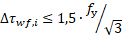
Both of the checks are true, as 85,44 MPa is less than 532,5 MPa (check for sigma) and 30 MPa is less than 307,44 (check for tau).
Step 5) Calculation Of Allowable Number Of Load Cycles
The fifth step consists of calculating the allowable number of load cycles per stress range. For this the following equations are needed.
The first equations is used in case the value of the stress range of concern is below the cut-off limit for normal stress ranges at the number of cycles NL: 
The second equations is used in case the value of the stress range of concern is in between of the cut-off limit for normal stress ranges at the number of cycles NL and the fatigue limit for constant amplitude stress ranges at the number of cycle ND: 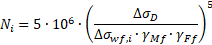
The third equation is used in case the value of the stress range of concern is above the fatigue limit for constant amplitude stress ranges at the number of cycle ND: 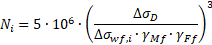
This results in the following values for the allowable numbers of load cycle:
|
|
σwf,i [MPa] |
τwf,i [MPa] |
ni |
Ni |
|
1 |
85,44 |
30 |
100.000 |
5,75E+06 |
|
2 |
63,25 |
20 |
400.000 |
2,84E+07 |
|
3 |
41,23 |
10 |
1.000.000 |
∞ |