Calculation Of Hot-Spot-Stress
Unfortunately, meshes with ideal aspect ratios are not always possible to create, which results in the element centres to be located off the extrapolation points which are recommended by the IIW. These locations are at 0.5*t and 1.5*t perpendicular to the weld, with t the thickness of the respective plate. Hence, stresses from out-off-line elements cannot be used directly for the extrapolation process for structural stresses as needed in Eurocode 3.
In those cases WeldFEM will calculate the relevant stresses in four steps:
Step 1) Locating the ideal elements
The first step includes locating the elements which centres are closest to the required extrapolation points.
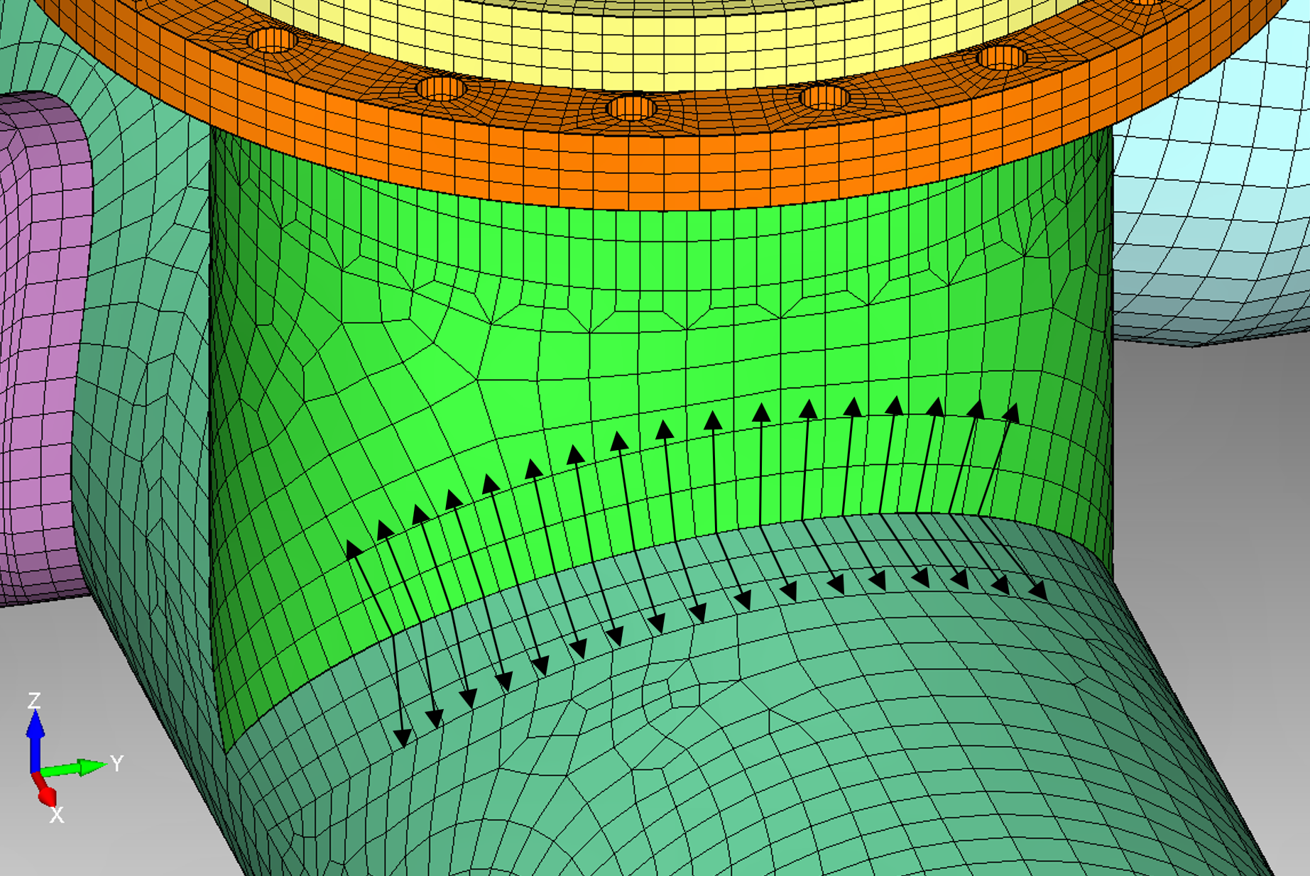
The extrapolation paths are always perpendicular to the weld and start at half the length of the element edge. This is shown in the following example, where two cylindrical pipes merge at their junction.
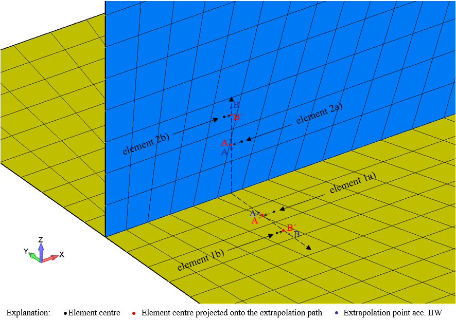
An example in detail for one extrapolation path is shown in the following figure. Here, it is depicted how the element centre, the projected element centre and the extrapolation points are located in a non rectangular mesh. For the example shown below, the elements 1a) and 1b) for the flange as well as 2a) and 2b) for the web have been identified by WeldFEM as elements used to provide the relevant extrapolation stresses.
Step 2) Transformation of the element stresses
Since the assessment for fatigue in Eurocode 3 is also based on stresses in the weld coordinate system, a transformation of the extracted element stresses has to be performed according to the description of Extraction And Transformation Of The Required Stress Values.
Step 3) Selection of stress type for extrapolation
Now that WeldFEM has determined the elements needed and has the transformed stresses available, the next step consists of selecting the right stress types for the extrapolation process. For that, the stress types in question need to be compared regarding their orientation relative to the weld and their absolute values.
The IIW recommends selecting the stress type based on the following:
- If the principal stress with the highest absolute value acts in an angle equal or less than 60° to the welds perpendicular direction, then this principal stress shall be taken for the extrapolation process.
- If this is not the case the normal stress perpendicular to the weld or the principal stress with the smaller absolute value shall be used. Which one of both, depends on which stress type presents the higher absolute value.
Step 4) Interpolating stresses
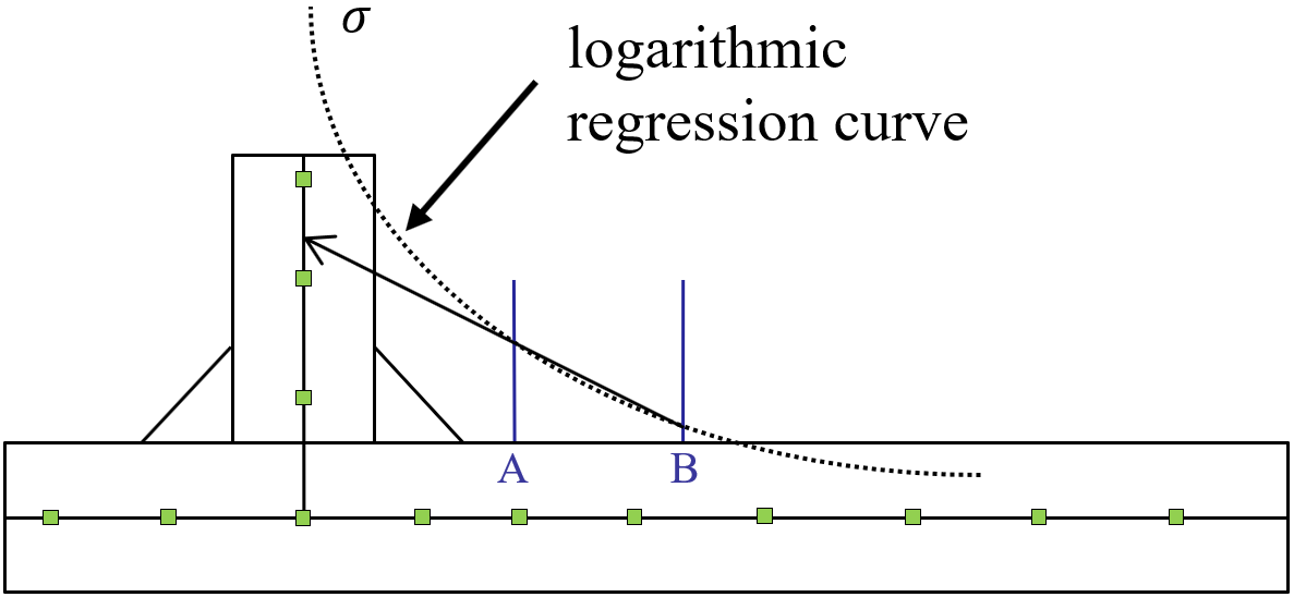
Now that WeldFEM has determined which stress types per element is needed, the interpolation process can be done. In order to use stresses at said extrapolation points according to IIW an fitting process is used first. For this, the assumption is made that the stress distribution perpendicular to the weld and along the sheet surface can be represented by a logarithmic regression curve, as shown in the following example.
Note: The example shown below does not present a noticeable increase in stress near the weld seam transition, because the stress distribution shown applies to the underlying FE-model and not the real structure. The real structure would show a stress peak at the weld seam transition because of the notch effect.
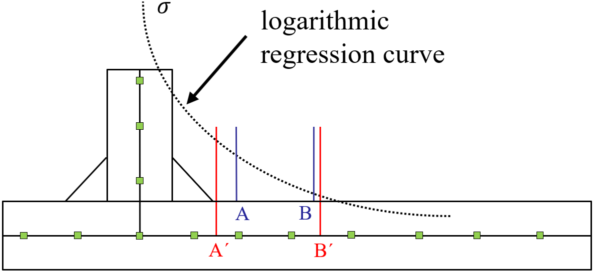
The logarithmic regression can be described by the following equation  . With the stresses at point A' and B' the parameters a and b can be determined. After determining both parameters, the stresses at the extrapolation points A and B can be calculated. The distance from the intersection of the mid-planes to the extrapolation points A and B is the input for the equation while the output will be the stresses at the extrapolation points, respectively.
Step 5) Extrapolation stresses
After WeldFEM determined the stresses at the extrapolation points A and B, the structural stress is calculated.
For this, WeldFEM extrapolates the stresses at point A and B linearly up to the intersection of the mid-planes, as shown in the figure below.